Product Description
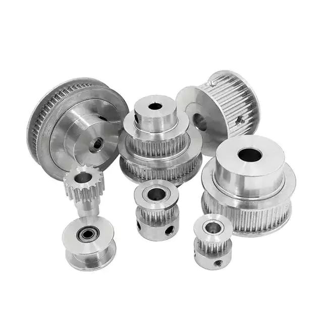
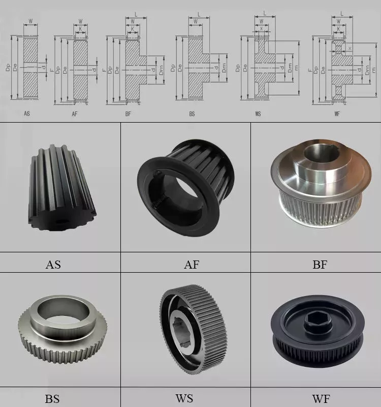
CZPT Machinery offers a wide range of high quality Timing Belt Pulleys and Toothed Bars/ Timing Bars. Standard and non-standard pulleys according to drawings are available.
Types of material:
1. AlCuMgPb 6061 6082 Aluminum Timing Pulley
2. C45E 1045 S45C Carbon Steel Timing Pulley
3. GG25 HT250 Cast Iron Timing Pulley
4. SUS303 SUS304 AISI431 Stainless Steel Timing Pulley
5. Other material on demand, such as cooper, bronze and plastic
Types of surface treatment
1. Anodized surface –Aluminum Pulleys
2. Hard anodized surface — Aluminum Pulleys
3. Black Oxidized surface — Steel Pulleys
4. Zinc plated surface — Steel Pulleys
5. Chromate surface — Steel Pulleys; Cast Iron Pulleys
6. Nickel plated surface –Steel Pulleys; Cast Iron Pulleys
Types of teeth profile
| Teeth Profile | Pitch |
| HTD | 3M,5M,8M,14M,20M |
| AT | AT5,AT10,AT20 |
| T | T2.5,T5,T10 |
| MXL | 0.08″(2.032MM) |
| XL | 1/5″(5.08MM) |
| L | 3/8″(9.525MM) |
| H | 1/2″(12.7MM) |
| XH | 7/8″(22.225MM) |
| XXH | 1 1/4″(31.75MM) |
| STS STPD | S2M,S3M,S4.5M,S5M,S8M,S14M |
| RPP | RPP5M,RPP8M,RPP14M,RPP20M |
| PGGT | PGGT 2GT, 3GT and 5GT |
| PCGT | GT8M,GT14M |
Types of pitches and sizes
Imperial Inch Timing Belt Pulley,
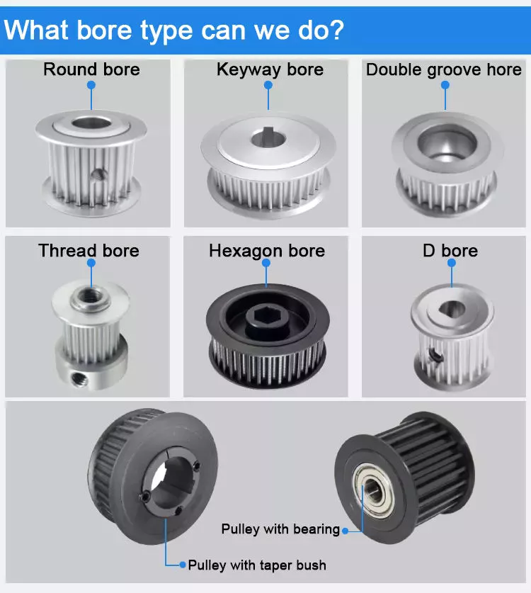
1. Pilot Bore MXL571 for 6.35mm timing belt; teeth number from 16 to 72;
2. Pilot Bore XL037 for 9.53mm timing belt; teeth number from 10 to 72;
3. Pilot Bore, Taper Bore L050 for 12.7mm timing belt; teeth number from 10 to 120;
4. Pilot Bore, Taper Bore L075 for 19.05mm timing belt; teeth number from 10 to 120;
5. Pilot Bore, Taper Bore L100 for 25.4mm timing belt; teeth number from 10 to 120;
6. Pilot Bore, Taper Bore H075 for 19.05mm timing belt; teeth number from 14 to 50;
7. Pilot Bore, Taper Bore H100 for 25.4mm timing belt; teeth number from 14 to 156;
8. Pilot Bore, Taper Bore H150 for 38.1mm timing belt; teeth number from 14 to 156;
9. Pilot Bore, Taper Bore H200 for 50.8mm timing belt; teeth number from 14 to 156;
10. Pilot Bore, Taper Bore H300 for 76.2mm timing belt; teeth number from 14 to 156;
11. Taper Bore XH200 for 50.8mm timing belt; teeth number from 18 to 120;
12. Taper Bore XH300 for 76.2mm timing belt; teeth number from 18 to 120;
13. Taper Bore XH400 for 101.6mm timing belt; teeth number from 18 to 120;
Metric Timing Belt Pulley T and AT
1. Pilot Bore T2.5-16 for 6mm timing belt; teeth number from 12 to 60;
2. Pilot Bore T5-21 for 10mm timing belt; teeth number from 10 to 60;
3. Pilot Bore T5-27 for 16mm timing belt; teeth number from 10 to 60;
4. Pilot Bore T5-36 for 25mm timing belt; teeth number from 10 to 60;
5. Pilot Bore T10-31 for 16mm timing belt; teeth number from 12 to 60;
6. Pilot Bore T10-40 for 25mm timing belt; teeth number from 12 to 60;
7. Pilot Bore T10-47 for 32mm timing belt; teeth number from 18 to 60;
8. Pilot Bore T10-66 for 50mm timing belt; teeth number from 18 to 60;
9. Pilot Bore AT5-21 for 10mm timing belt; teeth number from 12 to 60;
10. Pilot Bore AT5-27 for 16mm timing belt; teeth number from 12 to 60;
11. Pilot Bore AT5-36 for 25mm timing belt; teeth number from 12 to 60;
12. Pilot Bore AT10-31 for 16mm timing belt; teeth number from 15 to 60;
13. Pilot Bore AT10-40 for 25mm timing belt; teeth number from 15 to 60;
14. Pilot Bore AT10-47 for 32mm timing belt; teeth number from 18 to 60;
15. Pilot Bore AT10-66 for 50mm timing belt; teeth number from 18 to 60;
Metric Timing Belt Pulley HTD3M, 5M, 8M, 14M
1. HTD3M-06; 3M-09; 3M-15; teeth number from 10 to 72;
2. HTD5M-09; 5M-15; 5M-25; teeth number from 12 to 72;
3. HTD8M-20; 8M-30; 8M-50; 8M-85 teeth number from 22 to 192;
4. HTD14M-40; 14M-55; 14M-85; 14M-115; 14M-170; teeth number from 28-216;
5. Taper Bore HTD5M-15; 8M-20; 8M-30; 8M-50; 8M-85; 14M-40; 14M-55; 14M-85;
14M-115; 14M-170
Metric Timing Belt Pulleys for Poly Chain GT2 Belts
1. PCGT8M-12; PCGT8M-21; PCGT8M-36; PCGT8M-62;
2. PCGT14M-20; PCGT14M-37; PCGT14M-68; PCGT14M-90; PCGT14M-125;
Power Grip CZPT Tooth/ PGGT 2GT, 3GT and 5GT
1. 2GT-06, 2GT-09 for timing belt width 6mm and 9mm
2. 3GT-09, 3GT-15 for timing belt width 9mm and 15mm
3. 5GT-15, 5GT-25 for timing belt width 15mm and 25mm
OMEGA RPP HTD Timing Pulleys
1. RPP3M-06; 3M-09; 3M-15; teeth number from 10 to 72;
2. RPP5M-09; 5M-15; 5M-25; teeth number from 12 to 72;
3. RPP8M-20; 8M-30; 8M-50; 8M-85 teeth number from 22 to 192;
4. RPP14M-40; 14M-55; 14M-85; 14M-115; 14M-170; teeth number from 28-216;
5. Taper Bore RPP5M-15; 8M-20; 8M-30; 8M-50; 8M-85; 14M-40; 14M-55; 14M-85;
14M-115; 14M-170
| Certification: | ISO |
|---|---|
| Pulley Sizes: | Timing |
| Manufacturing Process: | Sawing |
| Material: | Aluminum 6061 |
| Surface Treatment: | Phosphating |
| Application: | Chemical Industry, Grain Transport, Mining Transport, Power Plant |
| Samples: |
US$ 3/Piece
1 Piece(Min.Order) | |
|---|
| Customization: |
Available
| Customized Request |
|---|

Three basic types of pulleys, their applications and ideal mechanical advantages
There are three basic types of pulleys: movable, fixed and compound. Each has its advantages and disadvantages, and you should be able to judge which type is best for your needs by looking at the table below. Once you have mastered the different types of pulleys, you can choose the right pulley for your next project. Now that you have mastered the three basic types, it is time to understand their applications and ideal mechanical advantages.
describe
The stress characteristics of a pulley depend on its size and construction. These stresses are derived by comparing the stress characteristics of different pulley designs. Stress criteria include static and fatigue strength analyses and specify maximum stress ranges. Stresses are calculated in a 3D stress field, including radial, tangential and axial stresses. The stress characteristics of pulleys are critical to the design and manufacture of industrial machines.
The principal stresses on the pulley shell are distributed in the tangential and hoop directions, close to the centerline of the pulley. If the pulley has a wide face, the axial stress occurring near the shell/disk junction can be large. The stress distribution was determined using British Standard BS5400 Part 10: Stresses at the shell and end disc connections for infinite fatigue life.
Another type of composite is a pulley with a belt section. Such structures are well known in the art. The corresponding help chapters for these elements contain detailed descriptions of the internal structure of these components. Chamfers between pulleys can also be defined using multiple tapers, with a smaller taper extending from midpoint 44 to large diameter 42. Additionally, the pulley can have multiple taper angles, and as the pulley moves away, the taper angle is from the center.
type
A pulley system uses a rope to move the object and one side of the rope to lift the load. The load is attached to one end of the pulley, while the other end can move freely in space. The force applied to the free end of the rope pulls the load up or down. Because of this, the mechanical advantage of the movable pulley is two to one. The greater the force applied to the free end of the rope, the greater the amount of movement achieved.
There are three common types of pulleys. The cast-iron variety has a rim at the front and a hub at the back. The arms of the pulley can be straight or curved. When the arms contract and yield instead of breaking, they are in tension. The top of the pulley centers the belt in motion and is available in widths ranging from 9mm to 300mm.
The rope, hub and axle are mounted on the pulley. They are common and versatile mechanical devices that make it easier to move or lift objects. Some pulleys change the direction of the force. Others change the magnitude. All types of pulleys can be used for a variety of different applications. Here are some examples. If you’re not sure which type to choose, you can find more resources online.
application
The applications for pulleys are almost limitless. This simple machine turns complex tasks into simple ones. They consist of a rope or chain wrapped around a wheel or axle. Using ropes, one can lift heavy objects without the enormous physical exertion of traditional lifting equipment. Some pulleys are equipped with rollers, which greatly magnifies the lifting force.
When used properly, the pulley system can change the direction of the applied force. It provides a mechanical advantage and allows the operator to remain separate from heavy objects. They are also inexpensive, easy to assemble, and require little lubrication after installation. Also, once installed, the pulley system requires little maintenance. They can even be used effortlessly. Despite having many moving parts, pulley systems do not require lubrication, making them a cost-effective alternative to mechanical lifts.
Pulleys are used in many applications including adjustable clotheslines in different machines, kitchen drawers and motor pulleys. Commercial users of pulley systems include cranes. These machines use a pulley system to lift and place heavy objects. They are also used by high-rise building washing companies. They can easily move a building without compromising its structural integrity. As a result, many industries rely on technology to make elevators easier.
Ideal mechanical advantage
The ideal mechanical advantage of a pulley system is the result of rope tension. The load is pulled to the center of the pulley, but the force is evenly distributed over the cable. Two pulleys will provide the mechanical advantage of two pulleys. The total energy used will remain the same. If multiple pulleys are used, friction between pulleys and pulleys reduces the return of energy.
Lever-based machines are simple devices that can work. These include levers, wheels and axles, screws, wedges and ramps. Their ability to work depends on their efficiency and mechanical superiority. The ideal mechanical advantage assumes perfect efficiency, while the actual mechanical advantage takes friction into account. The distance traveled by the load and the force applied are also factors in determining the ideal mechanical advantage of the pulley.
A simple pulley system has an MA of two. The weight attached to one end of the rope is called FA. Force FE and load FL are connected to the other end of the rope. The distance that the lifter pulls the rope must be twice or half the force required to lift the weight. The same goes for side-by-side pulley systems.
Materials used in manufacturing
While aluminum and plastic are the most common materials for making pulleys, there are other materials to choose from for your timing pulleys. Despite their different physical properties, they all offer similar benefits. Aluminum is dense and corrosion-resistant, and plastic is lightweight and durable. Stainless steel is resistant to stains and rust, but is expensive to maintain. For this reason, aluminum is a popular choice for heavy duty pulleys.
Metal can also be used to make pulleys. Aluminum pulleys are lightweight and strong, while other materials are not as durable. CZPT produces aluminium pulleys, but can also produce other materials or special finishes. The list below is just representative of some common materials and finishes. Many different materials are used, so you should discuss the best options for your application with your engineer.
Metals such as steel and aluminum are commonly used to make pulleys. These materials are relatively light and have a low coefficient of friction. Steel pulleys are also more durable than aluminum pulleys. For heavier applications, steel and aluminum are preferred, but consider weight limitations when selecting materials. For example, metal pulleys can be used in electric motors to transmit belt motion.
cost
Replacing a tensioner in a car’s engine can cost anywhere from $90 to $300, depending on the make and model of the car. Cost can also be affected by the complexity of the pulley system and how many pulleys are required. Replacement costs may also increase depending on the severity of the damage. The cost of replacing pulleys also varies from car to car, as different manufacturers use different engines and drivetrains.
Induction motors have been an industrial workhorse for 130 years, but their cost is growing. As energy costs rise and the cost of ownership increases, these motors will only get more expensive. New technologies are now available to increase efficiency, reduce costs and improve safety standards.
The average job cost to replace an idler varies from $125 to $321, including labor. Parts and labor to replace a car pulley can range from $30 to $178. Labor and parts can cost an additional $10 to $40, depending on the make and model of the car. But the labor is worth the money because these pulleys are a critical part of a car’s engine.


editor by CX
2023-04-23